Surface Layout
The Surface Layout root node and all its sub-nodes in the Tree View allows you to define the actors that play a role in the routing of fluids through the system: the facilities that process those fluids, the connections from wells to facilities or between facilities, and the constraints that capacity limits at individual facilities impose on how fluids flow through the system.
The node comprises three main tabs:
- The Surface Layout Tab, displaying a schematic layout of all surface facilities and connections.
- The Constraints Tab, which allows an overview of all constraints on the flow of fluids.
- The Pipelines Tab, which summarizes all connections for which costs and construction times have been defined. (See Pipelines.)
- The In Last Simulation tab (Surface Layout) provides a representation of the final state of the layout after the simulation has ended.
The Facilities sub-node contains a summary of all Facilities defined in the project, and a separate Facility Node for each.
Fluid Routing in PetroVR
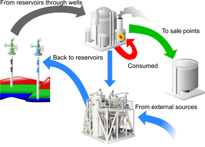
During a PetroVR simulation, produced hydrocarbons actually flow, in a way integrated with the simulation of scheduled jobs. This means that in the virtual world created by the simulation fluids go from reservoirs through wells prompted by their production profiles, and through the network of facilities to their final destination or back into the reservoirs (by means of injection). The material balance of the whole system is constantly guaranteed, i.e. the whole production is accounted for.
Each well knows, at every moment, what its cumulative production has been up to that point, and tries to yield the rate predefined production profile indicates for that specific production. But constraints in the system (such as a facility's processing capacity) must be resolved during the simulation itself and may put a limit to what the surface network can receive and process, scaling back if necessary part or all of the production; at any point in time, the well's actual production may be lower than its potential.
Now, hydrocarbons come out of reservoirs as three-phase and are eventually separated by specific facilities into oil, gas, water and other components, but if the system scales back part of the production, causing a well to choke, the three-phase does not get to be separated. Thus, choking e.g. the oil production of one well implies that its commingled production of oil, gas and water is scaled back proportionally. See Well Chokes for a detailed explanation of how chokes are addressed.
From the point of view of the routing, PetroVR facilities operate as passive objects sending downstream the fluids they receive. This process can only begin when a production line from development wells to a final destination (e.g. a sell point) is complete - that is, when all the facilities that may receive fluids from a given manifold are built and ready to produce. Until then, all wells feeding the incomplete production line are stopped even if they are already drilled and completed.
All the fluids routed come from the field (i.e., defined reservoirs) with two exceptions:
- Injection Facilities can have also an additional external source of gas or water to meet injection requirements.
- Facilities with Consumption defined automatically purchase the required fluid if not enough fluid from the field reach them.
Connection lines specify the direction of the routing. All facilities can receive and route any kind of fluid provided they have appropriate in/out connectors defined, but stream circularity is not allowed. A facility can receive a specific fluid from different sources, and send a specific source to more than one target; this last case constitutes Split Streams. Consumption of fluids and facility Downtime Simulation, on the other hand, each impact the routing system and must be carefully considered when designing the production and processing network.

